Table of Contents
Jabel
| Description | An electrical vehicle to transport heavy objects…. |
|---|---|
| Status | Running |
| Contact | fantawams,orimpe |
| Participants: | everybody |
As it is a pain in the ass to transport heavy stuff manually, it is a much smarter solution to transform a hoverboard into something, with which you can transport your stuff. Also you can recycle a hoverboard, as most of the time, the thing that is broker, is the gyro sensor or the battery.
Specs
Basic construction
- steel: 2mm strength
- size: 30mm x 30mm pipes
- place for stuff: 2 Mate crates length and 2 Mate crate wide (80cm x 60cmn)
- total weight maximum of 5kg without motor or batteries
Motor
- 4x4 hoverboard motors, each 250W sensored bruchless DC motors
Controller
- RF controller
- no power ⇒ stop (perhaps in version2)
Ideas for future versions
Realistic ideas
- led lights to see in the dark
- places to connect other Jabels or to fix stuff (perhaps in version 2), solution in the keep it stupid simple way
- suspension
- auto drive button (aka press button and it drives with walking pace forward)
- always on beeping
- switch to disconnect battery
- side pipes
- Jabel convoy
Crazy ideas
- able to sit on it and drive it like a car
- 8x8 offroad jabel
- towing hitch
Tips for future versions
- Buy the steel at Agrifer, they will cut the pieces as needed for a cheap price.
- Using not 2mm steel but 1 - 1.5 mm steel, to make it lighter.
- Making the metal construction out of aluminium to make it lighter. Thickness should than be at least 2mm to maximum of 3mm.
- Start and stop button, better position.
- Charge connector, better position.
Software
Building firmware
make
The Jabel is another form of the TranspOtter. The main difference here, is that the Jabel is using an RF controller and the TranspOtter is using Gametrack to navigate. Find in the Link also other Hoverboard hacks.
As we are using an RF controller, we need to slightly modify the firmware. So we open in the Inc folder the conf.h file and adjust the following. From:
// ############################### INPUT ###############################

// ###### CONTROL VIA UART (serial) ######
//#define CONTROL_SERIAL_USART2       // left sensor board cable, disable if ADC or PPM is used!
#define CONTROL_BAUD       19200    // control via usart from eg an Arduino or raspberry
// for Arduino, use void loop(void){ Serial.write((uint8_t *) &steer, sizeof(steer)); Serial.write((uint8_t *) &speed, sizeof(speed));delay(20); }

// ###### CONTROL VIA RC REMOTE ######
// left sensor board cable. Channel 1: steering, Channel 2: speed. Use a very short cable!
//#define CONTROL_PPM                 // use PPM-Sum as input. disable CONTROL_SERIAL_USART2!
//#define PPM_NUM_CHANNELS 6          // total number of PPM channels to receive, even if they are not used.

// ###### CONTROL VIA TWO POTENTIOMETERS ######
// ADC-calibration to cover the full poti-range: connect potis to left sensor board cable (0 to 3.3V) (do NOT use the red 15V wire in the cable!). see <How to calibrate>. turn the potis to minimum $
//#define CONTROL_ADC                 // use ADC as input. disable CONTROL_SERIAL_USART2!
#define ADC1_MIN 0                // min ADC1-value while poti at minimum-position (0 - 4095)
#define ADC1_MAX 4095               // max ADC1-value while poti at maximum-position (0 - 4095)
#define ADC2_MIN 0                // min ADC2-value while poti at minimum-position (0 - 4095)
#define ADC2_MAX 4095               // max ADC2-value while poti at maximum-position (0 - 4095)

// ###### CONTROL VIA NINTENDO NUNCHUCK ######
// left sensor board cable. keep cable short, use shielded cable, use ferrits, stabalize voltage in nunchuck, use the right one of the 2 types of nunchucks, add i2c pullups. use original nunchuck. $
//#define CONTROL_NUNCHUCK            // use nunchuck as input. disable DEBUG_SERIAL_USART3!

// ###### MOTOR TEST MODE ######
// slowly move both wheels forward and backward, ignoring all inputs
#define CONTROL_MOTOR_TEST
#define CONTROL_MOTOR_TEST_MAX_SPEED 300         // sweep slowly from -MAX_SPEED to MAX_SPEED (0 - 1000)
To:
// ############################### INPUT ###############################

// ###### CONTROL VIA UART (serial) ######
//#define CONTROL_SERIAL_USART2       // left sensor board cable, disable if ADC or PPM is used!
//#define CONTROL_BAUD       19200    // control via usart from eg an Arduino or raspberry
// for Arduino, use void loop(void){ Serial.write((uint8_t *) &steer, sizeof(steer)); Serial.write((uint8_t *) &speed, sizeof(speed));delay(20); }

// ###### CONTROL VIA RC REMOTE ######
// left sensor board cable. Channel 1: steering, Channel 2: speed. Use a very short cable!
#define CONTROL_PPM                 // use PPM-Sum as input. disable CONTROL_SERIAL_USART2!
#define PPM_NUM_CHANNELS 6          // total number of PPM channels to receive, even if they are not used.

// ###### CONTROL VIA TWO POTENTIOMETERS ######
// ADC-calibration to cover the full poti-range: connect potis to left sensor board cable (0 to 3.3V) (do NOT use the red 15V wire in the cable!). see <How to calibrate>. turn the potis to minimum $
//#define CONTROL_ADC                 // use ADC as input. disable CONTROL_SERIAL_USART2!
//#define ADC1_MIN 0                // min ADC1-value while poti at minimum-position (0 - 4095)
//#define ADC1_MAX 4095               // max ADC1-value while poti at maximum-position (0 - 4095)
//#define ADC2_MIN 0                // min ADC2-value while poti at minimum-position (0 - 4095)
//#define ADC2_MAX 4095               // max ADC2-value while poti at maximum-position (0 - 4095)

// ###### CONTROL VIA NINTENDO NUNCHUCK ######
// left sensor board cable. keep cable short, use shielded cable, use ferrits, stabalize voltage in nunchuck, use the right one of the 2 types of nunchucks, add i2c pullups. use original nunchuck. $
//#define CONTROL_NUNCHUCK            // use nunchuck as input. disable DEBUG_SERIAL_USART3!

// ###### MOTOR TEST MODE ######
// slowly move both wheels forward and backward, ignoring all inputs
#define CONTROL_MOTOR_TEST
#define CONTROL_MOTOR_TEST_MAX_SPEED 300         // sweep slowly from -MAX_SPEED to MAX_SPEED (0 - 1000)
Flashing the mainboard
It is possible on linux OS, we just could not get it working. So we are sadly using the windows way with the official ST-Link software.
Version 1.0
Need to know
The firmware allows to use the hoverboard motors up to 40km/h. For the Jabel this is not what we want. The Power of an motor can be used, to get either a higher top speed, as for the bobbycar, or to get a higher torque. As a higher torque would allow us to transport a higher load or simply transport the load better, as we can get more strength out of the motor, we will try to slightly increase the software current limit in the firmware. Depending on how you adjust the firmware, you can increase the power output of a motor from 250W to 800W. This does not only sound nice, but also brings risk with it. So keep in mind:
add quote from spiderman
The danger here is, that we are working with electrical motors. A higher torque means a higher current. The only thing, which is limiting the current in the motor is the internal resistance, which is very small, and reverse voltage, when the motor is spinning. When the motor is not spinning or slowly spinning, we only have our small internal resistance, so a too high current will burn the motors. This is of course something we want to absolutely avoid. Another aspect of a high current, is that the battery, cables and mainboard need to be able to handle such an electrical load.
Basic construction
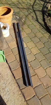
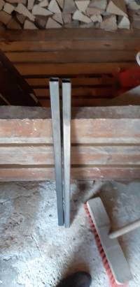
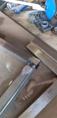
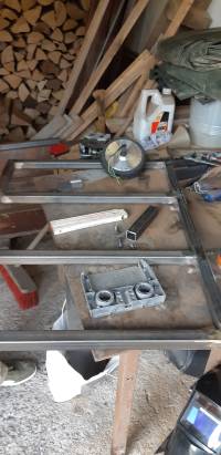
The basic construction is made out of steel with 2mm strength. We cut the 30mm pipes to the right sizes.
- 2x83cm pipes
- 4x57cm pipes add picture
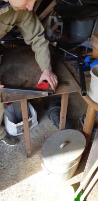
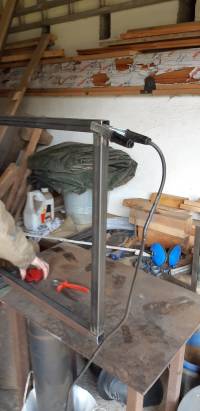
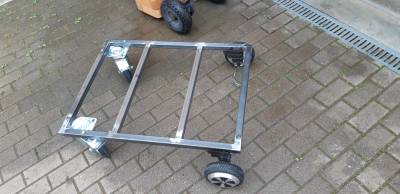
Than we welded 2x83cm pipes and 2x57cm pipes together, to have an chassis. The other 2 57cm pipes are used to have a sturdier chassis. It will be used to fix the batteries, mainboard and of course our bearing surface.
As we decided to use only 2 motors for the first version, we had to improvise a fix for the hoverboard motors. There is a height difference of 9cm between the front wheels and the hoverboard wheels. To have an aligned surface later on, we welded 3 spare pieces together to fix the hoverboard motors onto the chassis.
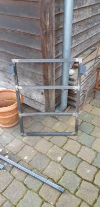
To be able to mount the front wheels and the hoverboard motors onto the chassis, we are using M8 screws. So we drill all the necessary holes into our chassis.
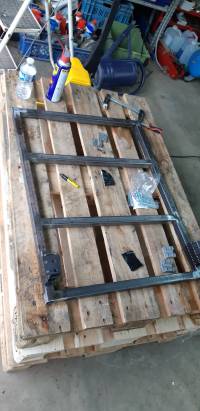
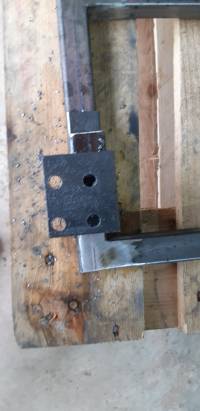
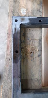
After this we simply mount all the wheels on it.
Wooden surface
The wooden surface is used to hold all the heavy stuff while transportation. 64,5cm x 84,5cm.
Battery
As we want to have enough energy to transport all the stuff with the Jabel, we need a power source that is strong enough. For this purpose we are going to build a battery out of old lithium-ion cells.
The original hoverboard battery, is a 10s2p battery with 18650 type lion cells. This means 10 cells in series with 2 in parallel. They have around 42V and offer around 4400mAh. This is enough for about 30 minutes of driving. As we want to increase this time, we simply need more energy stored in our battery. The maximum voltage a hoverboard mainboard can handle is around 55V.
Every battery should have an internal balancer to protect against:
- under voltage
- over current
- over temperature
battery build not clear for now:
- 10s4p
- 11s4p
- 12s4p
- 10s6p
- 11s5p ←
- 11s6p
- 12s6p
- 10s8p
- 11s8p
- 12s8p
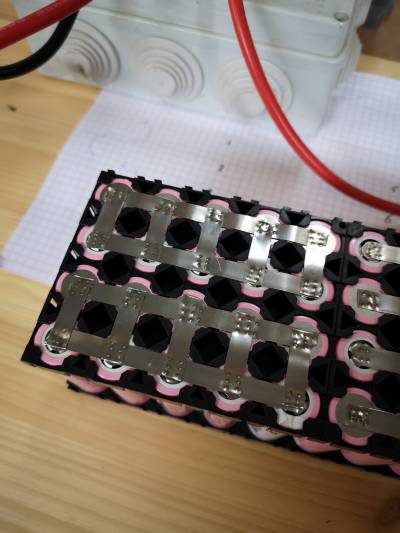
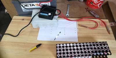 Hier der Aufbau während des zusammenbaus.
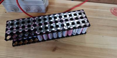 Fertiger Akku, jetzt fehlt nur noch das Batterie Management System (BMS)
Arbeitsmaterial
- Autosbatterie als Stromquelle
- Schere
- Nickelband
- alte Li Ion 18650 Zellen (in diesem Fall 55 Stück)
Battery case
Having a powerful battery is nice and fine, but without a case it will be difficult to mount it on the Jabel. It also serves a protection against stones, water and dirt.
PCB protection
The PCB mainboard needs a mechanical protection against water and dirt. For this purpose, we are using a medium junction box. It has enough space for the mainboard and reserve for other PCBs if needed.
Fancy stuff
As the Jabel is build by hackers and as hacker simply love LEDs, we are equipping it with LEDs and LED strips. These have not only the effect to make the whole thing look nice and fancy, but also have an useful purpose.Atnight you can still see where you are driving or simply see where the Jabel is.
